Quantcast
Channel: Sergei's incoherrent ramblings
Viewing all 58 articles
Browse latest View live

ILDVR – and their lack of professionalism

$
0
0

It all started with me purchasing ILDVR INC-MH40D06 IP Camera. I decided to poke at it and discovered some interesting and blatant security flaws.

About a year ago I contacted ILDVR (Arnold and Marika Wei) regarding the security issues, which got no response.
After about a year of the camera sitting on a shelf, I decided to poke at it again.
Which prompted me to send them this email:

For which I got a friendly response from Marika:

To which I replied, asking for firmware update (which I thought was reasonable to expect firmware updates for products with serious security flaws):

The only response I got is this peculiar email from sales@ildvr.com:

So, it seems that:
1) ILDVR.com/ILDVR does not care about security
2) ILDVR.com/ILDVR does not care about PR
3) ILDVR.com/ILDVR does not care about customers

Perhaps they should adopt the following motto:

“GO TO HELL! – ILDVR (where security does not matter)”.

To be honest, I would probably let go this whole thing if they simply not responded. It would have taken them less effort to not to respond either. Instead they chose to send me email with “GO TO HELL!”. I find this thing very hilarious.

It is even more hilarious if you look at google search results:


Cross-flash M1015/9420-8i LSI controller quasi-official way

$
0
0

WARNING: don’t blame me if you brick your card ;).

Building large cost effective storage solutions present a problem: lack of cost effective HBAs.
The solution to this problem is an interesting controller from IBM/Lenovo M1015. These can be bought for about 70USD on ebay.
The only problem with that controller is that the firmware it comes with (aka WebBIOS) is utter crap.
This problem can be resolved thanks to LSI providing alternative firmware images.

I generally flash these cards in Pass-Through mode, as they are not suitable for hardware raid scenario (lack of battery and RAM). Besides in low cost situation it is far better to use mdadm RAID (or ZFS) than hardware RAID (due to flexibility in reshaping, monitoring and fault recovery). With hardware RAID you simply cannot start with 3-disk RAID5 and grow it a disk at a time to 12-disk RAID6 without moving data to another storage.

I decided to write this guide as I could not find a guide that would use the tools and firmware images directly acquired from official sources (LSI/Avago/Broadcom).

All the guides include their own download links, which present security (malware) and possible bricking issues (if images were corrupted).

The goal of this guide is to stick to only files sourced from LSI (now Broadcom) as well as avoiding using Windows (Linux friendly).
By the time someone reads this the version and links will change so I am including search keywords on how to find the files in question.

I will be focusing on Pass-Through mode firmware (IT mode), but the only difference to IR mode is the 2118it.bin vs 2118ir.bin.

Preparation
* Before you start please be aware that the flash tools do not work on all CPU/Motherboard combinations. I had no luck with the motherboards that have Intel graphics chips. I had good success with Dell R610 server.
* You will need an USB flash disk.
* You are comfortable with linux shell
* Write down SAS number from back of the card! It will be in form of 500605B X-XXXX-XXXX

Tools needed:
* FreeDOS live USB (LSI Pre-Boot USB tool)
* megarec.exe
* dos4gw.exe
* sas2flsh.exe
* 2118it.bin
* mptsas2.rom

FreeDOS live USB
The FreeDOS live USB is available (officially!) from LSI, and found via this search:
LSI Pre-Boot USB tool
The LSI_PreBoot_Installer.7z is file of interest.

megarec.exe and dos4gw.exe
megarec.exe and dos4gw.exe are found via this search:
megaraid dos
The actual files of interested are:
MegaRAID SCSI MegaRC – DOS, Version 1.20
MegaRAID SAS MegaCLI – DOS, Version 1.01.39
Note: megacli.exe is not actually needed, only use of that download is to get dos4gw.exe. Alternative source of dos4gw.exe can be found here (just rename dos32a.exe to dos4gw.exe).

sas2flsh.exe, 2118it.bin and mptsas2.rom
sas2flsh.exe, 2118it.bin and mptsas2.rom are found via this search:
9211-8i msdos
The actual file of interest is:
9211_8i_Package_P20_IR_IT_FW_BIOS_for_MSDOS_Windows

sbrempty.bin
Since I could not find official source of empty SBR image I decided to generate it myself (based on multiple sources of this file)
The file looks like this:

0000000 0000 0000 0000 0000 0000 0000 0000 0000
*
0000090 0000 0000 0000 0000 ffff ffff ffff ffff
00000a0 ffff ffff ffff ffff ffff ffff ffff ffff
*
0000100

This can be generated using these two commands:
dd if=/dev/zero of=sbrempty.bin bs=152 count=1
dd if=/dev/zero bs=104 count=1 | tr "\000" "\377" >> sbrempty.bin

Live USB preparation.

1) Using your partitioner of choice create one fat32 DOS partition on a usb flash drive (I used 4GB drive).
2) Download LSI_PreBoot_Installer.7z and extract it into a directory.
3) copy ‘boot’ directory (extracted above) to the USB drive.
4) cd into boot/syslinux directory (extracted above) and chmod +x syslinux.
5) assuming your new created partition is /dev/sdb1 run following as root: dd conv=notrunc bs=440 count=1 if=mbr.bin of=/dev/sdb
6) set boot flag on the flash drive:
parted /dev/sdb set 1 boot on (this can also be done with a gui partition editor tool like gparted).
7) install syslinux on the flash drive (/dev/sdb1 must be mounted):
./syslinux -f -d /boot/syslinux /dev/sdb1. Note: this must be done from boot/syslinux extracted directory (not the OS version of syslinux).
8) create a directory in root of flash drive (lets assume it is named “firmware”)
9) Place megarec.exe, dos4gw.exe, sas2flsh.exe, 2118it.bin, mptsas2.rom and sbrempty.bin (see above for generation instructions) files into newly created directory (see above for download locations).
10) Safely remove drive ;).

Flashing instructions
Note: assuming only one LSI controller installed in the system. Don’t forget to get SAS number (500605BXXXXXXXXX) from the back of the card.

1) Boot into USB
2) Select FreeDOS option in the boot menu
3) Select Option 4 (no drivers) for FreeDOS
4) C: and cd firmware, dir to confirm all files are there (megarec.exe, dos4gw.exe, sas2flsh.exe, 2118it.bin, mptsas2.rom and sbrempty.bin)
5) save current SBR:
megarec.exe -readsbr 0 sbr.bck
this might be useful for recovery(?)
6) Write empty SBR:
megarec.exe -writesbr 0 sbrempty.bin
7) Clear flash:
megarec.exe -cleanflash 0
8) Reboot (important!).
9) repeat 1) through 4)
10) Set the controller into 6Gb/s mode:
sas2flsh -o -e 6
(Not sure if this step is necessary). Type in 2118it.bin when prompted for firmware image
11) Write new firmware:
sas2flsh -o -f 2118it.bin -b mptsas2.rom
12) Program original SAS address:
sas2flsh -o -sasadd 500605BXXXXXXXXX
Note: replace 500605BXXXXXXXXX with the number on your card (omit ‘-‘).
13) Done

As alternative sas2flsh tool exists for linux and all the sas2flsh steps could be done from comfort of your Linux distro.

Toyota Vitz RS and its disappointing throttle response

$
0
0

Recently we got a nice 2005 Toyota Vitz RS (NCP91) with a manual transmission.

It is great car in all aspects except power delivery and throttle response is pathetic.

We already have 1NZ-FE powered car in the family – Toyota IST and unlike the Vitz RS it is not that pathetic (in fact it is kind of fun to drive).
Yes, I have driven multiple Vitz RS and they were all asthmatic.
So what is so different between IST and RS? IST happens to have cable driven throttle, while RS has drive-by-wire.

Here is where Toyota screwed up and completely ruined the car: they made throttle map to emulate steam roller.

If I was Toyota I would not stick RS badge on the car, it is not a hot hatch simply because it lacks in engine department. Vitz RS should have came out with 1ZZFE at least.
What is even worse they decided to stick this anaemic throttle map on top. As if the car was not boring enough.

After consulting google and various forums I had two minor mod options:

1) Stick a throttle controller
2) Stick a throttle body off 1ZZFE.

I decided to go for second option as it is transparent from end user point of view. There are a few minor hurdles with this mod.

For one using 1ZZFE throttle body produces CEL/logged error. This is fixed by swapping control boards from 1NZFE to 1ZZFE body.

Second hurdle is that the coolant pipes are at different angle. I addressed this by sticking screwdriver and rotating outlet port to desired angle (it is press-fit).

Third hurdle is that the inlet rubber hose is a bit too small to fit 1ZZFE throttle body. This is rectified by dab of grease and brute force.

Forth hurdle is that 1ZZFE throttle body outlet is a bit larger than the intake manifold inlet. I haven’t yet addressed it. I plan to get a thin (4-5mm) plate made up with a slope gradually joining two diameters (the diameter difference is about 10mm, thus the lip will have 45 degree slope). Another alternative fix is to get another manifold and grind out the hole to the 1ZZFE diameter (while epoxy-ing and flattening surface to accept regular gasket). This option is a bit extreme.

The result was significant. The throttle response was as if it was cable driven. It is like going from I mode to S# mode on an WRX STI. It also lost the power gap after 5k, the engine revved more freely right through to red line.

Details…

The throttle conversion:
Fronts. Left is 1ZZFE and right is 1NZFE:

Backs. Left is 1NZFE and right is 1ZZFE:

Part numbers (1NZFE: 22030-21030; 1ZZFE: 22030-22041):

1NZFE is about 51mm ID at the front:

1ZZFE is about 60mm ID at the front:

Going from 1NZFE to 1ZZFE gains about 9mm at the front.

1NZFE is about 46mm ID at the back:

1ZZFE is about 56mm ID at the back:

Going from 1NZFE to 1ZZFE gains* about 10mm at the back.
* Not true: as the inlet manifold sized at 46mm ID. This will need to be addressed somehow.

The controller board for 1NZFE has DENSO 105 E21 printed:

The controller board for 1ZZFE has DENSO 105 F12 printed:

Combining 1NZFE controller board with 1ZZFE body:

Complete 1NZFE/1ZZFE hybrid body:

Installation:

There is not much in the way:

Contradictory (in my opinion) to online information the factory air box is actually of a nice design, there is even a bell on the inlet:

Once air box and inlet pipe is remove factory throttle is ready for removal:

Before I proceeded, I test fitted the inlet pipe to see if I can actually stretch it to fit much larger throttle body. Yes it did fit with lots of brute force and small amount of grease:

Because throttle body has coolant lines going through it (for de-icing purposes, utterly pointless in NZ climate). To stop coolant leaking out I used 8mm drill bits as plugs (whatever fits ;)):

Removing upper throttle body nuts and freeing up the coolant neck reveals another set of nuts:

Removing throttle body reveals sealing arrangement and, what seems to be, a flame arrester:

Note: the manifold has 46mm opening, matching the original throttle body.
This creates a problem that will have to be addressed in future – the step is visible here:

It appears that even with partial coverage of O-ring there weren’t any vacuum leaks (yet ;)).

1ZZFE throttle body in place with coolant hoses attached (one port had to be rotated with force):

A very tight fit of the inlet pipe:

In conclusion the overall result is great, the engine became more lively. Of course actual performance gain is probably minimal, but at least the car no longer has Tiida dynamics.

I used to be a fan of Toyotas when they made things like Starlet GT, Corolla GT etc, ie actual hot hatches. Vitz RS is not a hot hatch. Now Toyota is only making boring appliances, which is a shame.

HUSQVARNA rip-off pricing in NZ

$
0
0

So, I came across an interesting, but not surprising thing with Husqvarna MSRP prices in NZ compared to USA.

I recently looked at Husqvarna 445 and when googled for it, I got multiple MSRP prices (one for NZ, on for AU and another for USA).

Husqvarna 445 MSRP by country:
USA: 329.95 USD

AU: 899.00 AUD (~$690 USD)

NZ: 1019.00 NZD (~$745 USD)

According to NZ customs duty calculator using US MSRP price as base the fair MSRP price in NZ should have been $599 NZD (~$440 USD).

What is with the ~$150 USD price difference between NZ and Australia? According to Husqvarna Americans are twice better than Australians and more than twice better than Kiwis. They treat Kiwis like chumps that will buy thing at whatever prices Husqvarna feels like.

Guess what, from now on I will be avoiding the Husqvarna until these greedy corporate types will pull their heads out of their asses and set fair MSRP prices. In this global economy it is very stupid not to have standardised prices across the globe.

If I really wanted to buy one, no way in hell I would be buying it in NZ, as for about $150NZ I can get it shipped from the states.

Toyota Vitz RS throttle swap sorting out bugs

$
0
0

This is a follow up to this post.

After a few weeks of testing the throttle body swap the following issues have surfaced:

1) Very high idle on cold start up (>3000rpm)
2) Random idle oscillations (cold and warm start up)
3) Abrupt overrun transition

I suspected two things that could cause these issues.

1) Air leak due to improper seal between 56mm throttle opening and 46mm intake manifold (the throttle would only partially cover the O-ring)
2) The default opening of the throttle body was set too high (due to being set for 1.8L engine).

To remedy air leak issue I have ordered a water cut aluminium plate. I used onestopcuttingshop.co.nz for water cutting.
The plate is 8mm thick. The onestopcuttingshop.co.nz supplied the aluminium, total cost was just under $60 (NZD) including shipping.

Here are the files I made for water cutting:
Dimensions
Plate

To remedy the idle oscillations all I needed to do is to adjust default opening of the throttle. The adjustment screw is on “top” of the throttle sealed with epoxy resin.

Here is the received water cut plate:

I have marked out 55mm for filing in the tapper/funnel (slightly under 55.6mm of the 1ZZFE throttle opening):

Test fit the blank against the spare 1NZFE throttle body to ensure there is nothing interfering:

Hand filing throttle progress:

To make sure even finish I frequently rotated the plate in the vice and changed direction.

Test fit the filed plate:

Applied thin coat of sealant on one surface (between throttle body and the plate):

Note: there is no need to apply sealant between manifold and plate as I retained existing O-ring.

Checking for step, unfortunately there is still 1mm step, but I think it is close enough as hand filing is a very time consuming for such small thing:

Here is where the “idle” adjuster (not really idle adjusting but more of a starting position):

The adjuster screw mostly freed from epoxy (using a fine flat screwdriver as a pick):

Using 2mm Allen key I turned ~3 times in total counter clockwise to reduce default opening angle so the ECU would not overshoot on initial startup:

Best way to adjust this is to do it while the ignition is in OFF position, one turn at a time (or even half turn), starting the engine and checking max RPM: it should be below 2000 on warm engine and drop below 1000 couple of seconds after start.

This is what the plate looks like from outside:

Note: I left out two nuts between the coolant pipe bracket and throttle body, thus removing the need to replace the studs with longer.

As last thing I pulled out 7.5A ECU-B fuse for a few seconds to kick-off learning of the idle. I left it idling until it completely warmed up to give ECU plenty of time to learn.

At this stage this mod removed all the idle issues.

I will cover the adjustment screw with RTV once I am sure that oscillation are completely gone during the cold start.

External Western Digital USB drives and why to avoid them

$
0
0

Today I encountered a dead Western Digital USB 2.5″ drive.
The drive in question is “WD 1TB Elements SE Portable Hard Drive USB 3.0” with WDBPCK0010BBK-01 part number.
Searching for the part number on WD site leads nowhere.

The error was:

 Buffer I/O error on dev sdb, logical block 0, async page read 

So it appeared that the drive would respond to ATA commands but unable to actually read data off the platters.

Here is more detailed log:

[2938633.261938] usb 2-2.1: new SuperSpeed USB device number 6 using xhci_hcd
[2938633.282496] usb 2-2.1: New USB device found, idVendor=1058, idProduct=1042
[2938633.282498] usb 2-2.1: New USB device strings: Mfr=1, Product=2, SerialNumber=5
[2938633.282499] usb 2-2.1: Product: Elements 1042
[2938633.282500] usb 2-2.1: Manufacturer: Western Digital
[2938633.282502] usb 2-2.1: SerialNumber: 575846314137323034313835
[2938633.283578] usb-storage 2-2.1:1.0: USB Mass Storage device detected
[2938633.283952] scsi host3: usb-storage 2-2.1:1.0
[2938634.290551] scsi 3:0:0:0: Direct-Access     WD       Elements 1042    1015 PQ: 0 ANSI: 6
[2938634.291200] sd 3:0:0:0: Attached scsi generic sg1 type 0
[2938634.292545] sd 3:0:0:0: [sdb] Spinning up disk...
[2938635.313869] .
[2938636.337934] .
[2938637.361956] .
[2938638.385900] .
[2938639.409882] .
[2938640.433854] .
[2938641.457909] .
[2938642.481939] .
[2938643.505886] .
[2938644.529870] .
[2938645.553905] .
[2938646.577852] .
[2938647.601902] .
[2938647.602483] ready
[2938647.602738] sd 3:0:0:0: [sdb] 1953519616 512-byte logical blocks: (1.00 TB/932 GiB)
[2938647.603163] sd 3:0:0:0: [sdb] Write Protect is off
[2938647.603169] sd 3:0:0:0: [sdb] Mode Sense: 47 00 10 08
[2938647.603454] sd 3:0:0:0: [sdb] No Caching mode page found
[2938647.603465] sd 3:0:0:0: [sdb] Assuming drive cache: write through
[2938827.614004] sd 3:0:0:0: timing out command, waited 180s
[2938827.614011] sd 3:0:0:0: [sdb] tag#0 FAILED Result: hostbyte=DID_OK driverbyte=DRIVER_SENSE
[2938827.614012] sd 3:0:0:0: [sdb] tag#0 Sense Key : Hardware Error [current] 
[2938827.614014] sd 3:0:0:0: [sdb] tag#0 Add. Sense: Internal target failure
[2938827.614015] sd 3:0:0:0: [sdb] tag#0 CDB: Read(10) 28 00 00 00 00 00 00 00 08 00
[2938827.614017] blk_update_request: I/O error, dev sdb, sector 0
[2938827.614019] Buffer I/O error on dev sdb, logical block 0, async page read

I decided to pull it apart to see what I could salvage (I well knew because it was WD most likely I would not have a SATA drive in there).

Complete utter rubbish! The drive as expected was not SATA drive with separate USB controller. No way you could pull the drive out of the enclusre and try it on SATA interface for ddrescue.

Do not buy WD external drives!

So, the only good thing I got out of that dead drive is a micro USB 3.0 cable and a plastic enclosure for some electronic project. The enclosure is useless as hard drive enclosure due to lack of actual SATA to USB controller.

Perhaps it could be converted to E-Sata with some USB power? Not worth it.

UPDATE: found potential problem:

These corroded contacts connecting controller board with head/internal components. Another reason not to buy WD as they were too cheap to use gold plated contacts.

Cleaning them up does not fix the issue, unfortunately:

I assume something burned out (either as side effect of oxidised contacts or contacts are just a symptom).

Replacing timing chain tensioner on a 1NZFE

$
0
0

Since day one of our ownership of this particular 1NZFE powered Toyota IST the engine was a bit on louder side.
Previously all my other cars had timing belts and I put it down to simply being a “feature” of chain.
After more family and friends upgraded their cars to xNZFE, it was clear that this engine was slightly louder in chain department then the rest (especially in the mornings).

One day after coming back from a holiday I started the car only to be greeted by loud chain slapping noise.

OMG! My wife’s car turned into a Nissan!

I decided to exorcise the Nissan out of it by replacing the chain tensioner and guides.

Below is how I did it, not necessary the “correct” way. This process took about 6 hours, good chunk of it was spent on cleaning the surfaces.
It was pretty much like replacing timing belt, except with way more RTV.
Over all I replaced two oil pump O-rings, front crank seal, valve cover gasket, both chain guides and chain tensioner.

In retrospect I prefer timing belts as opposed to timing chains, especially considering that the tensioners still fail on chains occasionally.

Interesting notes:

  • Old guides were PA66, new guides are PA46 (improved)
  • Old tensioner had larger oil hole than the new tensioner.
  • In hand old tensioner functioned correctly, but while fitted it would skip.
  • For some reason Toyota decided it is great idea to incorporate water pump flange into front cover. This creates a potential of RTV failure and leakage of coolant into sump. It also requires pump removal when removing front cover. It would saved me 2 hours if the pump was not part of the front cover.
  • The oil pump is mounted on front cover, thus requiring two O-rings for inlet and outlet.
  • One of those O-ring was completely flat, possibly leaking oil. It is hard to tell if the O-rings seated properly when fitting the cover.
  • For the crank pulley Toyota gone away from woodruff key in favour of tiny hollow pin.
  • The 10mm cover bolts and water pump bolts torqued at 11Nm. The 12mm cover nut and bolts torqued at 24Nm. The crank pulley went in hella-tight with crappy rattle gun and on top with some hammer on spanner action (It should be 128Nm). The tensioner and guides bolts are torqued to 9Nm.
  • I used Threebond grey RTV. The manual specified two kinds of RTVs for water pump and the rest of the cover, good luck buying two Toyota genuine RTV tubes ;).

Slack Before and After:


The chain tensioner and guides are located behind the front cover of the engine. To remove front cover all the stuff around it needs to be removed including the valve cover.

To remove the valve cover I disconnected coils and injectors (mainly so I can get the loom out of the way):

On the bottom of the car I removed the plastic mud guard to expose the crank pulley:

To remove the engine mount first support the engine with a good jack:

Undo the two bolts on top of the mount:

Undo the single nut on the bottom of the mount:

Then undo three more bolts that bolt the mount to the chassis:

To get to the engine side mount bracket the water pump pulley must come off:

The mount bracket is held by 4 bolts, here is the bracket removed:

The crank pulley bolt came off with a regular compressed air rattle gun (to my surprise!). Alternative method would have been using starter and long breaker bar:

To remove the power steering pump belt one needs to undo this particular bolt:

I used my own crank pulley removal “tool”:

The whole pulley is located by this tiny hollow pin:

Pulley gone, exposing the crank angle sensor and other stuff:

Crank angle sensor connector is a bitch to disconnect unless you know how to slide this white tab:

Crank angle sensor gone, as well as most of the cover bolts:

Almost forgot to drain coolant (this can be done in the beginning). The drain plug is located on radiator. The drain plug drains into an outlet to which you can attach a hose:

After draining the coolant I removed the water pump and moved the alternator out of the way:

To remove the valve cover I removed the coils:

And it is gone (after gently prying it off, as well as some rubber mallet action):

It takes a lot of patience to unseal the front cover. Do not forget about a bolt right in the middle of the cover! Be very careful when prying it off as it can crank in half. I gently pried it off, starting from the top and continuing to the bottom. The water pump side required extra taps to get going:

For some reason Toyota decided it is great idea to locktite couple of water pump studs… With them in place it is impossible to remove the front cover. I had to resort to the counter double nut technique to remove these bastards:

Here is a view to the old guides and the tensioner:

Oddly the inlet timing marks only match the top marks (there is also a dot closer to the centre, which I assume indicates the top mark):

Exhaust timing mark (note double dotted mark to the top).

Note: there are corresponding notches on the cam shaft journal carrier.

Crank shaft timing marks are not as clear, I assume double dot must align to the oil jet:

New chain follower fitted:

New chain tensioner and followers fitted:

New oil seal fitted:

RTV galore:

Note: make sure oil pump is completely free of oil, otherwise it would drip on the RTV and ruin the seal.

Cover fitted:

Crank pulley, sensor and water pump fitted:

Cleaned the valve cover and fitted new gasket:

Make sure to leave a dab of RTV where the front cover joins the head (don’t forget to do the back side):

Cover on:

Rest is just bolting on the stuff and filling up the coolant.
It was a success as it is the quietest 1NZFE, in the chain department at least ;).

Beware of fake Philips HID Bulbs!

$
0
0

I decided to replace the 6300k HID bulbs on one of my cars, with more sensible 4300k OEM solution.

I came across reasonably priced Toyota Genuine Bulbs on trademe.co.nz (NZ ebay type of thing).

The particular bulbs I was after were D4R, or Toyota Genuine Part 90981-20015 (alternatively Philips 42406).

They were priced (~$80NZD) similar to Genuine Philips 42406 in USA (~$50USD), so seemed to be reasonable. The Toyota Genuine are after all Philips 42406 in TGP box.

When I tried to fit the bulbs I noticed they were extremely tight. Then I looked closely and did some googling.

I found this video from http://www.hidconcept.com:

The video convinced me that these bulbs were fakes.

I contacted Philips NZ the best way I could, through their lighting department. Unfortunately I got handled by an unsavoury character that pretty much told me to pound sand.
He told me that Philips NZ officially does not sell these bulbs in NZ thus I need to contact Hella. When I told him that it is a pretty much a non-reply, he told me to contact Repco or Supercheap. I avoid buying anything from Repco or Supercheap if there is a choice. Especially Repco.
Once I finish this post I will be sending the link to Philips NZ PR/Media department, because at this stage I feel Philips NZ does not give a shit about the brand.

Here is the conversation:
I basically asked (with photos attached) if the bulbs are real or not:

Reply was not what I was hoping for: I was flogged off to Hella (as far as I am concerned Hella is 2nd tier competitor):

I pressed further:

Instead of giving me a contact in Philips who can verify, he tells me to pound sand:

I point out that Philips does actually market these bulbs in New Zealand:

He does not get it (or care), and sends me off to a random 3rd party:

So, I tried again to get through to him, and plainly asked for contact in Philips:

In complete (but not surprising) utter disappointment he gives me a spiel about reputable source:

Since the Philips NZ was a no-go, I contacted Philips USA with actual success!

This is not a D4R bulb that we distribute, looking at the serial number on the bulb, it is not in the same order as the numbers on the bulbs that we distribute. That could make the bulb counterfeit. Unfortunately, we will not be able to assist with a bulb that was not distributed by our distribution center.

So, this was as good as anything I could get out of Philips. I take it as confirmation as the bulb being fake.

I got extremely curious and I decided to buy real genuine Philips 42406 from http://www.hidconcept.com. The difference is phenomenal! They are also richer and warmer in colour and brighter. So the fakes were not even true 4300k.

So lets go back to initial cause of suspicion – tight fit:

Real bulb measured 24.78mm in diameter at the base:

Fake bulb on other hand measured 25.12mm in diameter at the base:

Here is side by side comparison:


Note: very bad spot welds, missing dimple in the glass body, crooked and thin font. Also locating slot is cut too deep.


Note: bottoms are very different in colour and castings. Unlike other reports this fake had a number on the bottom (barely visible).


Note: another angle on the font.


Note: rough edges on fake, probably diamond cut and snapped. Real has a nice smooth laser cut.


Modifying rear fog light into a functional second set of stop and park lights on a Forester SJG

$
0
0

For some silly reason a JDM Forester XT (SJG) comes with a single rear fog light on right side (and a dummy on left side).

I am amazed that these rear fog lights are not disabled during compliance. They are useless, annoying and illegal in NZ.
Too many times I was stuck behind an oblivious BMW driver in rain only to be blinded by their rear fog lights.
In my opinion these people who drive with rear fog lights should be fined.

So, the rear fog light got to go.

Since I did not want to have a lower row of lights to be completely useless I decided to convert them to another stop/park light set. At same time I replaced all the bulbs with LED lights.

The only thing that I need to purchase is a set (2x) of 7443 sockets. One small mistake was ordering the sockets with 4 clips (vs 3 clips), thus not only needed to drill and cut out dummy side, I also needed to modify the fog light side to accept 4 clip socket. I could not reuse the fog light socket due to it being 2 wire (as I wanted fully functional light, not just stop).

Results, before and after (Stop lights, reverse and indicator on):

The process.

Light is only held by two screws (use 10mm socket, even though the fasteners also have JIS “+” slot):

Disconnect loom:

On left light:

Here is what the dummy light looks on the back:

I marked with soldering iron indent for easy drilling of pilot hole:

Drilled pilot hole for hole saw:

Drilled 21mm hole with hole saw (carefully, as it is possible to smash through):


Test fitted the socket:

On both sides:

Spliced, soldered and heat shrunk the wires (note: the Green-White wire is for stop):

Drilled corners for locator slots with 2mm drill bit:

Then cut them with sharp blade:

On right side I cut and heat-shrunk the fog light wires:

Note: thoroughly vacuum inside of the lights to get rid of the plastic debris left from drilling and cutting!

Bonus content.

Fog light up close:

Dummy light up close:

Part numbers:

Hikvision applied shotgun to the foot and squeezed the trigger

$
0
0

I guess I will not be recommending Hikvision any more to anyone.

Here is why:
http://www.hikvision.co.uk/faq_80.html
https://goo.gl/2uTtHk

So in short, Hikvision decided to only sell their cameras to authorized installers. The same installers that want $800 for $80 camera.
Well guess what, screw you Hikvision this is not pre-internet era where greedy corporation can dictate what is happening on the market.
I guarantee that this move will not curb prevalence of Chinese sourced cameras on ebay and aliexpress.
Granted this only affects UK and EU. I think this is just a beginning.

I personally will not be buying Hikvision and will definitely advising against buying Hikvision (be that from authorized rip-off artists or aliexpress).

As a company you should not screw with enthusiasts, as the same enthusiasts will be making purchasing decisions for their employers, and you will be losing many million of dollars at the end of the day. I am glad we went with Dahua.

Here is the full spiel:

August 2017

To Our Valued Customers,

As is well known, professional HIKVISION products are highly technical devices that require substantial product knowledge for the best possible system design, installation, support, and maintenance that our customers and end users deserve. Unfortunately, a large amount of products now are acquired from unauthorized channels and are not valid, up to date, or genuine HIKVISION products and accessories with qualified warranty or technical support.

For your protection, and to ensure you receive the best advice, technical support, and genuine HIKVISION products and accessories, HIKVISON is proceeding to build the selective distribution program in EU and UK (hereinafter referred as “HIKVISION Selective Distribution Program”), a new way different from generally intensive and exclusive distribution.

For HIKVISION Selective Distribution Program, HIKVSION establishes a set of criteria for authorized distributors (hereinafter referred as “Authorized Wholesalers”)and authorized system integrators/installers (hereinafter referred as “AuthorizedSystem Integrators/Installers”)(“Authorized Wholesalers” and “Authorized System Integrators/Installers” together referred as “Authorized Partners”), who are required to meet certain criteria and responsibilities mandated by HIKVISION. This includes not limited to the establishment and maintenance of the service staff, facilities, plant and equipment at one or more locations suitable for the satisfactory maintenance and repair of the HIKVISION Products. In other words, only the one who meet the relevant criteria can be the Authorized Partners, which HIKVISON products can only be bought and sold by, including online and offline. And the Authorized Wholesaler will only operate at the wholesale level of trade, and shall not sell the Products to end-users and the Authorized System Integrator/Installer will sell the HIKVISION Products to end-users at the retail level.

When becoming an Authorized Partner, you are able to leverage the HIKVISION partner portal, comprehensive multi-year warranty, and online project registration program. Also, you will have access to HIKVISON pre-sales support for sales questions, configuration and design assistance for the registered projects.

HIKVISION Selective Distribution Program will protect Authorized Partners that have invested the time and resources into becoming and maintaining their authorized status and in being knowledgeable in HIKVISION products to provide the best products choices to protect our customers.

Vendors who fail to meet its criteria or violate HIKVISION Selective Distribution Program by selling products to the unauthorized wholesalers/system integrators/installers after prior notification by HIKVISION are automatically moved to the Unauthorized Wholesalers/Systems Integrators/Installers.

To be our Authorized Partners, please contactus for complete criteria.

For more questions about this Program,please feel free to contact us at sales.uk@hikvision.com

Part 1: Implementing communication protocol for GT06E GPS tracker – WTF is CRC-ITU???

$
0
0

Preamble:

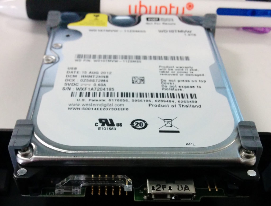
As an experiment I bought a relatively cheap GPS tracker that supported 3G (most of them at the time were 2G only).
After quick google search I found a suitable model GT06E from Concox.

The idea was I would implement my own server, as I do not trust 3rd party GPS tracking services (who would?), especially free ones ;).

I did not realise at the time what a mess the protocol is.
The “engineers” who wrote the spec for the protocol are crazy! They reinvented the wheel, which instead of tyre utilizes boots.

Ugly stuff:

So here are interesting quirks I found:

Setting server in GPS tracker to UDP has no effect, it only speaks TCP (firmware bug).

GPS tracker sends position data only when it is moving!!! This is very stupid. It also makes testing very difficult. There is no way to request the position data as if it was moving. Every time I needed to test, I had to pick it up and go for a walk.

Instead of using simple POST or even GET (with payload in URL) with HTTP protocol, the “engineers” decided to reinvent the wheel with their own protocol.
The GPS tracker mostly uses 0x7878 start sequence and 0x0d0a end sequence (sometimes it is 0x7979, fuck yeah!).
The payload also contains payload size (depending on start sequence it is either 1 byte or 2 bytes, with 0x7979 being latter), packet type, protocol payload, serial, and most importantly and what this post is about a checksum.

It is really bizarre why they decided to come up with their own protocol, which turned out to be very inconsistent between models. For example the GT06E is not exactly the same as GT06, and is very different to GT02. The way the data stored is also inconsistent, sometimes it is ASCII, sometimes it is binary, sometimes they only use portion of two bytes.

Unfortunately I could not find complete documentation for GT06E (mainly I was using GT06 protocl documentation).

The position data is bizarre. Instead of using signed ints for latitude and longitude, they use unsigned ints and then include the hemisphere as couple of bits in the course data (two bytes).

But even before we get to decoding payload we cannot communicate with the tracker unless we reply with correct checksum. They re-implemented 3 way hand shake with checksums and sequence numbers. I wonder if they are even aware how TCP works?

WTF is CRC-ITU?

To reply to the handshake packet (not to be confused with TCP handshake, it all happens above that) from the tracker one needs to be able to calculate checksum for the payload.

The documentation states that the checksum is calculated using CRC-ITU algorithm. It also provides a C example of it and a magical table:

static const U16 crctab16[] =
{
0X0000, 0X1189, 0X2312, 0X329B, 0X4624, 0X57AD, 0X6536, 0X74BF,
0X8C48, 0X9DC1, 0XAF5A, 0XBED3, 0XCA6C, 0XDBE5, 0XE97E, 0XF8F7,
0X1081, 0X0108, 0X3393, 0X221A, 0X56A5, 0X472C, 0X75B7, 0X643E,
0X9CC9, 0X8D40, 0XBFDB, 0XAE52, 0XDAED, 0XCB64, 0XF9FF, 0XE876,
0X2102, 0X308B, 0X0210, 0X1399, 0X6726, 0X76AF, 0X4434, 0X55BD,
0XAD4A, 0XBCC3, 0X8E58, 0X9FD1, 0XEB6E, 0XFAE7, 0XC87C, 0XD9F5,
0X3183, 0X200A, 0X1291, 0X0318, 0X77A7, 0X662E, 0X54B5, 0X453C,
0XBDCB, 0XAC42, 0X9ED9, 0X8F50, 0XFBEF, 0XEA66, 0XD8FD, 0XC974,
0X4204, 0X538D, 0X6116, 0X709F, 0X0420, 0X15A9, 0X2732, 0X36BB,
0XCE4C, 0XDFC5, 0XED5E, 0XFCD7, 0X8868, 0X99E1, 0XAB7A, 0XBAF3,
0X5285, 0X430C, 0X7197, 0X601E, 0X14A1, 0X0528, 0X37B3, 0X263A,
0XDECD, 0XCF44, 0XFDDF, 0XEC56, 0X98E9, 0X8960, 0XBBFB, 0XAA72,
0X6306, 0X728F, 0X4014, 0X519D, 0X2522, 0X34AB, 0X0630, 0X17B9,
0XEF4E, 0XFEC7, 0XCC5C, 0XDDD5, 0XA96A, 0XB8E3, 0X8A78, 0X9BF1,
0X7387, 0X620E, 0X5095, 0X411C, 0X35A3, 0X242A, 0X16B1, 0X0738,
0XFFCF, 0XEE46, 0XDCDD, 0XCD54, 0XB9EB, 0XA862, 0X9AF9, 0X8B70,
0X8408, 0X9581, 0XA71A, 0XB693, 0XC22C, 0XD3A5, 0XE13E, 0XF0B7,
0X0840, 0X19C9, 0X2B52, 0X3ADB, 0X4E64, 0X5FED, 0X6D76, 0X7CFF,
0X9489, 0X8500, 0XB79B, 0XA612, 0XD2AD, 0XC324, 0XF1BF, 0XE036,
0X18C1, 0X0948, 0X3BD3, 0X2A5A, 0X5EE5, 0X4F6C, 0X7DF7, 0X6C7E,
0XA50A, 0XB483, 0X8618, 0X9791, 0XE32E, 0XF2A7, 0XC03C, 0XD1B5,
0X2942, 0X38CB, 0X0A50, 0X1BD9, 0X6F66, 0X7EEF, 0X4C74, 0X5DFD,
0XB58B, 0XA402, 0X9699, 0X8710, 0XF3AF, 0XE226, 0XD0BD, 0XC134,
0X39C3, 0X284A, 0X1AD1, 0X0B58, 0X7FE7, 0X6E6E, 0X5CF5, 0X4D7C,
0XC60C, 0XD785, 0XE51E, 0XF497, 0X8028, 0X91A1, 0XA33A, 0XB2B3,
0X4A44, 0X5BCD, 0X6956, 0X78DF, 0X0C60, 0X1DE9, 0X2F72, 0X3EFB,
0XD68D, 0XC704, 0XF59F, 0XE416, 0X90A9, 0X8120, 0XB3BB, 0XA232,
0X5AC5, 0X4B4C, 0X79D7, 0X685E, 0X1CE1, 0X0D68, 0X3FF3, 0X2E7A,
0XE70E, 0XF687, 0XC41C, 0XD595, 0XA12A, 0XB0A3, 0X8238, 0X93B1,
0X6B46, 0X7ACF, 0X4854, 0X59DD, 0X2D62, 0X3CEB, 0X0E70, 0X1FF9,
0XF78F, 0XE606, 0XD49D, 0XC514, 0XB1AB, 0XA022, 0X92B9, 0X8330,
0X7BC7, 0X6A4E, 0X58D5, 0X495C, 0X3DE3, 0X2C6A, 0X1EF1, 0X0F78,
};
// calculate the 16-bit CRC of data with predetermined length.
U16 GetCrc16(const U8* pData, int nLength)
{
U16 fcs = 0xffff;
 // initialization
while(nLength>0){
fcs = (fcs >> 8) ^ crctab16[(fcs ^ *pData) & 0xff];
nLength--;
pData++;
}
return ~fcs;
 // negated
}

I refuse to accept black boxes and magic in general, so I went digging. Turns out this is described in RFC1331 with great detail.

Disclaimer: I know nothing!

So how does this magical tables comes to be? Math!

Here is the table generation algorithm I wrote based on the sample from the RFC1331:

def gen_fcs_table():
    table=[]
    P=0x8408
    b=0
    v=0

    while True:
        v=b
        i=8
        while i>0:
            if v&1:
                v=( v>>1 ) ^ P
            else:
                v=v >> 1
            i=i-1
        table.append(v & 0xFFFF)
        b=b+1
        if b==256:
            break
    return table

There is only one more “black box” left -> P=0x8408.
What we need to know is that the polynomial chosen for this CRC algorithm is x**0 + x**5 + x**12 + x**16.
The process of going from x**0 + x**5 + x**12 + x**16 to 0x8408 is described in detail on wikipedia

The simplest way I see it is following:
Map each power in polynomial on 0..16 sequence:

  0  1  2  3  4  5  6  7  8  9 10 11 12 13 14 15 16

so it looks like this (basically 1 under 0, 5, 12, and 16):

  0  1  2  3  4  5  6  7  8  9 10 11 12 13 14 15 16
 1  0  0  0  0  1  0  0  0  0  0  0  1  0  0  0  1

For this particular implementation we group the result in nibbles of 4 bits from left side (and throwing away remainder):

 [1  0  0  0 |0  1  0  0 |0  0  0  0 |1  0  0  0] 1

Which then is converted in binary, which results in 0x8408.

What is left is to implement the actual checksum algorithm:

def get_fcs(data, table):
    fcs=0xFFFF
    for i in data:
        b,=struct.unpack_from('>B',i)
        fcs=(fcs >> 8) ^ table[(fcs ^ b) & 0xFF]
    return fcs ^ 0xFFFF

From this point it is possible to assemble a simplest reply, in this fashion:

ADV_START=0x7979
STOP=0x0d0a
fcs_table=gen_fcs_table()

def tx_login(serial,prot,start):
    pre=struct.pack('>H',start)
    if start == ADV_START:
        payload=struct.pack('>BHH',0x05,prot,serial)
    else:
        payload=struct.pack('>BBH',0x05,prot,serial)
    check= get_fcs(payload,fcs_table)
    post=struct.pack('>HH',check,STOP)
    return pre+payload+post

to be continued…

mod_python: 404 on *.py when trying to download the file

$
0
0

I had mod_python enabled and it would give me 404 on random python scripts in downloads directory (not cgi)…
Nothing in error log either!

Here is the fix:

put .htaccess file in the download directory with following contents:

<Files *.py>
    RemoveHandler .py
    AddType text/plain .py
    SetHandler none
    SetHandler default-handler
    Options -ExecCGI
</Files>

Testing an engine knock sensor with multimeter and a hammer

$
0
0

No, I am not suggesting to hammer the knock sensor ;).

Recently I was diagnosing a very intermittent error code 52 (knock sensor open/closed circuit) on a 4AFE powered Toyota Corolla.
I needed a way to test the actual functionality of the knock sensor in a garage.

From my understanding a typical knock sensor is pretty much a condenser microphone. So measuring resistance of it pretty much meaningless beyond finding a completely stuffed one. The repair manual suggest that the resistance of one should be above 1 MOhm, as it should be, as it is a capacitor.

One requirement for this kind of crude testing is having a multimeter that does capacitance testing in the nF range.

The particular knock sensor I was testing measured at about 6-7nF (temperature dependant) sensor alone, or ~7.5nF with the wiring.

The test is very simple, I have unplugged the sensor from the ECU, plugged one probe form the multimeter (set to Capacitance range) to the pin for the knock sensor on the ECU plug, and another on chassis/earth/ground. Then I knocked on a random bolt on the engine block and watch the measurment:

This resulted an increase of the capacitance for each knock (to over 8nF).

Another test that is not on the video, is basically using rattle gun on a bolt. This produced over 1.5nF increase.

I have also tested the sensor outside in a vice while heating it up with heat gun to 120 degrees C. The capacitance increased by ~2nF during heating. The sensor responding in similar way as above to light knocks on the vice anvil.

Alternative and more sophisticated way of testing is hooking up sensor to the microphone input on a cellphone/Laptop/PC but that would involve butchering a 3.5mm jack.

Caveat Emptor: Do not buy EVGA GTX1060 6GB with ACX 2.0 Cooler!

$
0
0

What is wrong with EVGA GTX1060 6GB ACX2.0 (06G-P4-6161-KR)? Well, the cooler is a piece of shit and this card easily hits 90’C.

This is the card in question: 06G-P4-6161-KR

In addition if you are into ethereum mining, between 3 of those cards I could only get 17.8MH/s from each, which is far cry from 26MH/s from other brands of GTX1060. Which suggest they used crappiest RAM chips they could lay their hands on.

I have tried contacting EVGA to buy an ACX3.0 cooler from them and they told me they do not sell parts to retail.

Why would EVGA put inadequate heat sink on one model and a good heat sink on other model, while selling them for $20 difference is beyond me.
Sounds like they are cutting corners to earn an odd buck.

Dear EVGA: Fuck you! There are plenty of other brands to buy from.

I wish I found this post before I foolishly bought these cards:

PSA: Don’t buy the single fan EVGA GTX 1060 Gaming (non-SC) from pcmasterrace

In fact from now on I will never buy EVGA.

Simple IMAP to IMAP migration/sync tool

$
0
0

I had a need for a simple IMAP to IMAP sync tool, yet the only useful things I could find were offlineimap and imapsync.
The offlineimap is too complex and does not exactly do what I want; while the latter went commercial and not is not a clean install (requires messing with CPAN/perl libraries).

How hard can it be to write one?

Here it is:
imap2imap.py

The configuration is fairly simple (and self explanatory):

imap2imap.conf


hostname=outlook.office365.com
username=microsoftsucks@example.com
password=hunter12
trash=Deleted Items
#movetotrash=yes
#delete=yes

[destination]
hostname=imap.gmail.com
username=dontbeevil@gmail.com
password=hunter12

Here how it works:

It logs in into both IMAP servers and basically copies (with optional source deletion) the messages across. It also avoids duplication by checking Message-ID header. It should be stable enough to “daemon”-ify.

Here is a systemd unit for it (if one wants it to run all the time):

/etc/systemd/system/imap2imap.service

[Unit]
Description=IMAP to IMAP sync tool
After=network.target

[Service]
Type=simple
User=nobody
WorkingDirectory=/usr/local/bin/
ExecStart=/usr/local/bin/imap2imap.py
Restart=on-failure

[Install]
WantedBy=multi-user.target

Hate ads on your smart phone? Pi-hole it permanently!

$
0
0

Sorry about spammy headline ;).

Below I will describe how I got rid of ads on my android phone without rooting it.
It is very easy to get rid of ads on an android smart phone if you have root access. Unfortunately pesky manufacturers insist on declining warranty if the phone is rooted.
I will probably one day test this is in small claims court for a cheaper phone. I digress…

The requirements:

  • Some linux box/container/VM. In this post I used Ubuntu 16.04 LTS
  • Public IP on the box from above
  • Some linux/cli/unix experience

How does it work?

  1. Smart phone connects to the Linux box via OpenVPN
  2. Linux box is running Pi-hole which acts as a selective DNS server
  3. ???
  4. Proft!

Build.

OpenVPN:

1) Install OpenVPN and easy-rsa:
apt-get install openvpn easy-rsa

2) Setup easy-rsa depository:
make-cadir ~/ca
cd ~/ca

3) Configure easy-rsa:
emacs vars

Modify the following to match your set up:
export KEY_COUNTRY="NZ"
export KEY_PROVINCE="North Island"
export KEY_CITY="Auckland"
export KEY_ORG="pihole.example.com"
export KEY_EMAIL="pihole@example.com"
export KEY_OU="pihole.example.com"
export KEY_NAME="pihole"

4) Set up the environment:
source vars
./clean-all

5) Build CA, the server key and DH:
./build-ca
./build-key-server server
./build-dh

6)Copy the certs and keys to the OpenVPN directory:
cd keys
cp ca.crt server.crt server.key dh2048.pem /etc/openvpn

7) Create OpenVPN config:
echo "port 1194
proto udp
dev tun
ca ca.crt
cert server.crt
key server.key
dh dh2048.pem
server 10.12.34.0 255.255.255.0
ifconfig-pool-persist ipp.txt
push "redirect-gateway def1 bypass-dhcp"
keepalive 10 120
comp-lzo
user nobody
group nogroup
persist-key
persist-tun
status openvpn-status.log
verb 3
mute 20
cipher AES-128-CBC" > /etc/openvpn/server.conf

8) Start the OpenVPN server:
systemctl start openvpn@server.service

Note: Steps 1) through 8) needs to be done only once.

9) Build client key and cert:
./build-key client0

10) Because android OpenVPN client is very limited from configuration point of view and can only import pkcs12 keys (and does not “understand” inline certs), one needs to “pack” the CA cert, client cert and key into pkcs12 file:
openssl pkcs12 -export -in client0.crt -inkey client0.key -certfile ca.crt -name client0 -out client0.p12

11) Create client config (replace server after “remote” to your server domain name or IP):
echo "client
dev tun
remote pihole.example.com
resolv-retry infinite
nobind
persist-key
persist-tun
verb 1
keepalive 10 120
port 1194
proto udp
comp-lzo
cipher AES-128-CBC" > client0.ovpn

12) Securely copy the two files (client0.ovpn and client0.p12) to the android phone in question.

13) Install and configure the OpenVPN client on android. The config is imported by selecting “OVPN Profile” and using the import to import OVPN file and PKCS#12 certificate. The UI might differ, generally the import function can be accessed from “hamburger” menu.
Note: When importing the PKCS#12 certificate you will have to set pin/pattern (I don’t think there is work around for that).

14) On first connection the OpenVPN app will prompt which certificate to use with connection, make sure select the one that was imported in step 13).

Note: Steps 9) through 14) have to be repeated for each client; make sure to change the file name (client0 in this example) to something else for next client.

At this stage the OpenVPN tunnel in itself is functional but will not pass traffic through (see IPTABLES section).

Pi-Hole:

To install Pi-Hole one simply runs this:
curl -sSL https://install.pi-hole.net | bash
and follows on screen prompts.

IPTABLES:

To pass the traffic through the following rules needs to be set up:

  • MASQUERADE (aka as NAT): iptables -t nat -A POSTROUTING -s 10.12.34.0/24 -o eth0 -j MASQUERADE
  • Enable forwarding: echo "net.ipv4.ip_forward=1" >> /etc/sysctl.conf; sysctl -p

The above is basic minimum needed for tunnel to pass the traffic.

The evil thing that android does is completely ignores DNS servers given by DHCP, thus we will need to intercept that at the firewall level:
iptables -t nat -A PREROUTING -i tun0 -p udp -m udp --dport 53 -j DNAT --to-destination 10.12.34.1:53
Without the above pi-hole will not have any effect!

I would recommend having some other firewall rules to actually secure the linux box, being lazy I use post-up /usr/local/bin/firewall.sh in the interfaces file to set up the firewall where the /usr/local/bin/firewall.sh (don't forget to chmod +x /usr/local/bin/firewall.sh) looks something like this:
#!/bin/bash
IPTABLES=/sbin/iptables

$IPTABLES -P INPUT ACCEPT
$IPTABLES -P OUTPUT ACCEPT
$IPTABLES -P FORWARD ACCEPT
$IPTABLES -F
$IPTABLES -X
$IPTABLES -t nat -F
$IPTABLES -t nat -X
$IPTABLES -t mangle -F
$IPTABLES -t mangle -X
$IPTABLES -t raw -F
$IPTABLES -t raw -X

$IPTABLES -t nat -A PREROUTING -i tun0 -p udp -m udp --dport 53 -j DNAT --to-destination 10.12.34.1:53
$IPTABLES -t nat -A POSTROUTING -s 10.12.34.0/24 -o ens160 -j MASQUERADE

$IPTABLES -A INPUT -i lo -j ACCEPT
$IPTABLES -A INPUT -m state --state INVALID -j DROP
$IPTABLES -A INPUT -i tun0 -j ACCEPT
$IPTABLES -A INPUT -p icmp -j ACCEPT
$IPTABLES -A INPUT -p udp -m udp --dport 1194 -j ACCEPT
$IPTABLES -A INPUT -m state --state RELATED,ESTABLISHED -j ACCEPT

$IPTABLES -P INPUT DROP
Warning: The above does not deal with ssh and will promptly lock you out 😉 (unless you have existing session running to fix the screw-up).

Conclusion:

This set up has other advantages beyond the ad blocking:

  • IP blocking (via iptables or ipsets) on top of DNS blocking
  • Ensures security when captive portals and other insecure networks are used
  • Prevents overzealous employers from snooping DNS

Although this set up comes with some disadvantages:

  • Might not work well under bad networking conditions
  • Requires a machine on the internet that runs 24/7 (cloud/electricity costs)
  • Minor annoyance of having OpenVPN running all the time on the phone

On top of regular ad blocking this set up allowed me to block the whole facebook, which is a huge win.

GT06E GPS Tracker Part 2: Establishing connection

$
0
0

This is a continuation from Part 1.

As of writing this I already had complete solution (as far as getting tracking data is concerned), a multi-process TCP server with a mysql database back-end.
The server code itself is not pretty thus I am cautious about sharing it at this stage (I will “open-source” it once I cleaned it up).

One caveat: my solution does not support batch mode (where the payload contain multiple concatenated location and other packets).

The assumption is that the reader is somewhat familiar with python and sockets.

In this part I will focus on the initial and subsequent replies to the packets from trackers.
Due to nature of the “protocol” if the replies are not properly formed the tracker will drop the connection. Thus it is crucial to get it right.

For convenience I setup the following “constants”:

START=0x7878
ADV_START=0x7979
STOP=0x0D0A
PROTOCOL= {
    'login':0x01,
    'location':0x12,
    'status':0x13,
    'string':0x15,
    'alarm':0x16,
    'gps':0x1A,
    'command':0x80,
    'adv_string':0x94
}

Unfortunately due to closeness of the manufacturer the only way I could glimpse at the detail of the protocol is by googling the following phrases:
“GT06 protocol” and “GT02 protocol”. This site was very helpful.
I suggest to read the protocol description before trying to understand WTF is going on with my code. BTW: the GT06 is not the same as GT06E, and protocol slightly differs (thus I also included GT02).

When a tracker connects it sends a login packet. I process the login packet in the following way:

def rx_reply(data):
    payload = None
    serial = None
    dstart = None
    prot = None
    if data:
        dstart, = struct.unpack_from('>H',data)
    else:
        print("Skipping empty packet! @rx_reply() : '%s'" % binascii.hexlify(data))
        return False
    if dstart == START:
        elength = len(data)-5
        length, = struct.unpack_from('>B',data,2)
        if (elength) != length:
            print("Skipping packet with incorrect length; expected: 0x%02x (%d), received: 0x%02x (%d)!" % (elength,elength,length,length))
            return False
        dstop, = struct.unpack_from('>H',data,(length+3))
        if dstop != STOP:
            print("Skipping packet with incorrect stop sequence; expected: 0x%04x, received: 0x%04x!" % (STOP,dstop))
            return False
        prot, = struct.unpack_from('>B',data,3)
        serial,dcheck, = struct.unpack_from('>HH',data,(length-1))
        check = get_fcs(data[2:(length+1)],fcs_table)
        if check != dcheck:
            print("Skipping packet with incorrect check sum; expected: 0x%04x, received: 0x%04x!" % (check,dcheck))
            return False
        if prot == PROTOCOL['status']:
            payload = process_status(data[4:(length-1)])
        elif prot == PROTOCOL['string']:
            clength,serverid, = struct.unpack_from('>BI',data,4)
            eclength=length-8
            if clength != eclength:
                print("Skipping packet with incorrect command length; expected: 0x%02x (%d), received: 0x%02x (%d)!" % (eclength,eclength,clength,clength))
            payload, = struct.unpack_from(">%ds" % (clength-4),data,9)
        elif prot == PROTOCOL['location']:
            payload = process_location(data[4:(length-1)])
        else:
            payload = {'raw':binascii.hexlify(data[4:(length-1)])}
    elif dstart == ADV_START:
        elength = len(data)-6
        length, = struct.unpack_from('>H',data,2)
        if (elength) != length:
            print("Skipping packet with incorrect length; expected: 0x%02x (%d), received: 0x%02x (%d)!" % (elength,elength,length,length))
            return False
        dstop, = struct.unpack_from('>H',data,(length+4))
        if dstop != STOP:
            print("Skipping packet with incorrect stop sequence; expected: 0x%04x, received: 0x%04x!" % (STOP,dstop))
            return False
        prot, = struct.unpack_from('>B',data,4)
        serial,dcheck, = struct.unpack_from('>HH',data,(length))
        check = get_fcs(data[2:(length+2)],fcs_table)
        if check != dcheck:
            print("Skipping packet with incorrect check sum; expected: 0x%04x, received: 0x%04x!" % (check,dcheck))
        payload = data[5:(length-1)]
    else:
        print("Skipping packet with unknown start sequence; received: 0x%04x!" % dstart)
    if not serial:
        print("Received garbage hex: '%s' ascii %s" % (binascii.hexlify(data),repr(data)))
    return (serial,payload,prot,dstart)

Note: the length check will fail the batch packet and disconnect. Disable the batch mode or write a splitter function and batch packet detection logic. The get_fcs function and fcs_table are described in part 1.

Once I have serial, IMEI and protocol type I reply the following way:

def tx_login(serial,prot,start):
    pre=struct.pack('>H',start)
    if start == ADV_START:
        payload=struct.pack('>BHH',0x05,prot,serial)
    else:
        payload=struct.pack('>BBH',0x05,prot,serial)
    check= get_fcs(payload,fcs_table)
    post=struct.pack('>HH',check,STOP)
    return pre+payload+post

The simplest way to make this work is following:

serial,payload,prot,start = rx_reply(sock.recv(256))
imei=payload['raw']
sock.send(tx_login(serial,prot,start))

In next part I will describe decoding the location data and misc data (as much as I could find documentation for it).

Dealing with data obfuscation in some Chinese dash cameras

$
0
0

This is post relates to the extracting GPS coordinates form Novatek based dash cameras.

About an year ago I was contacted by someone who tried to use my script on MP4 files generated by their camera, only to get garbage data out. It appeared that the camera was obfuscating the coordinates stored in MP4 (the speed and heading was recorded correctly). It was not a bug because provided player was decoding them correctly.

I have spent few hours on this problem and given up as I could not see the pattern in the coordinates. As far as I was concerned it was one off and obscure enough not to worry about it.

Recently I got contacted by George G. with exactly same problem. This time I decided to really look into it.

Again, I hit a brick wall by just looking at the floats that the camera recorded, as they absolutely made no sense as coordinates in any known coordinate systems.

So the answer must be in the player. The player is called JMS GPS DVR Player.

Because I have no Windows machines I got friend to decompile the .exe file with jetbrains decompiler. That did an awesome job and I got fully readable C# code out if. At first I though I hit a jackpot when I saw some de-obfuscation going on but that turned out to be Chinese standard obfuscation and not the one I was looking for.

The jetbrains decompiler could not handle the GPSDataPraser.dll (not my typo ;)). Fortunately, previously I got it decompiled on Linux with retdec.

Having both, clear C# sources and messy retdec generated C code for the DLL I worked my way backwards from C#, on how it was calling the DLL. What initially prompt me to look into C# code for the algorithm is that on glance the DLL had no float/double arithmetic going on.

Working backwards allowed me to see this two pieces of code being executed on chunks of MP4 read by the DLL:

int128_t v20 = __asm_movss(*(int32_t *)(g9 + 72)); // 0x100023f5
int128_t v21 = __asm_subsd(__asm_cvtps2pd(v20), 0x40a12e65c3dee782); // 0x100023fe
int128_t v22 = __asm_cvtpd2ps(__asm_mulsd(v21, 0x3fe0000000000000)); // 0x1000240e

and

int128_t v23 = __asm_movss(*(int32_t *)(g9 + 68)); // 0x1000241d
int128_t v24 = __asm_subsd(__asm_cvtps2pd(v23), 0x40677f6defc7a398); // 0x10002426
int128_t v25 = __asm_cvtpd2ps(__asm_divsd(v24, 0x4008000000000000)); // 0x10002436

This was found on line 1064 of the decompiled C “code”. I found it by looking for decimal values (ASCII) of ‘A’ and ‘V’, after the point the file was read. And there it was:

if (v72 != 86) {

It was looking if the value of char of not being ‘V’, as the GPS provides the valid data as ‘A’ and invalid data as ‘V’ I suspected I was in the right place.

When I saw that the value was converted into double precision float (aka double) and subdivision was done to it I knew I struck gold.

These bastards were doing basic arithmetic to obfuscate the coordinates so their end users are forced to use their crappy JMS GPS DVR player. I consider that a dick move.

Here is the translation the assembly/c into human readable presentation of the crappy obfuscation.

For longitude they use following two constants:

0x40a12e65c3dee782 -> 2199.19876 and 0x3fe0000000000000 -> 0.5.

To get longitude:
longitude = (obfuscated_longitude - 2199.19876) * 0.5

For latitude they use following two constants:

0x40677f6defc7a398 -> 187.98217 and 0x4008000000000000 -> 3.

To get latitude:
latitude = (obfuscated_latitude - 187.98217) / 3

Death and Resurrection of Asus RT-N16

$
0
0

One day the faithful Asus RT-N16 suddenly died.
Power supply was swapped yet there were no lights.

Post-mortem examination revealed a swollen capacitor (16V 680uF).

Bad 16V 680uF C110 cap

Due to double sides board with lots of vias, and crappy RoHS solder, de-soldering required hot air gun.

C110 gone.

I didn’t have 16V 680uF capacitor handy, so I improvised with a very tall 25V 1000uF capacitor. Again, solder would not take with soldering iron, only with hot air gun.

New C110. Improvised with placement as it was too tall .

I have checked the rest of the caps (on board) and they were all within the spec.

The router came alive after C110 replacement.

It’s alive!

Measuring the bad cap resulted in ~92uF…

680uF? Not even close.

idiot

Viewing all 58 articles
Browse latest View live